

The delivery, installation and commissioning as well as the modernisation of existing winders is an integral part of WINDER CONTROLS South Africa’s core business.
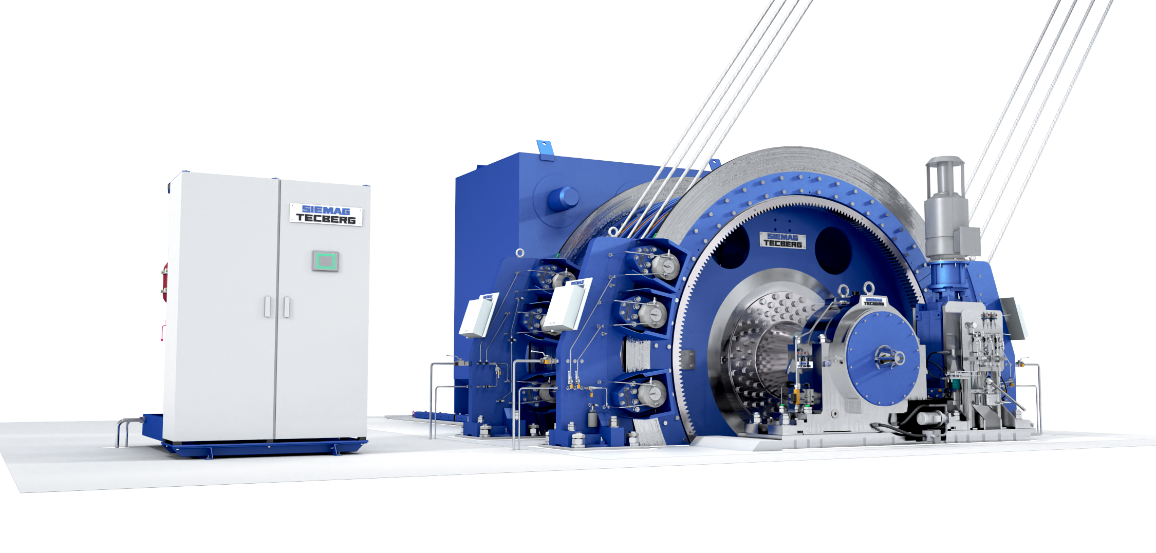
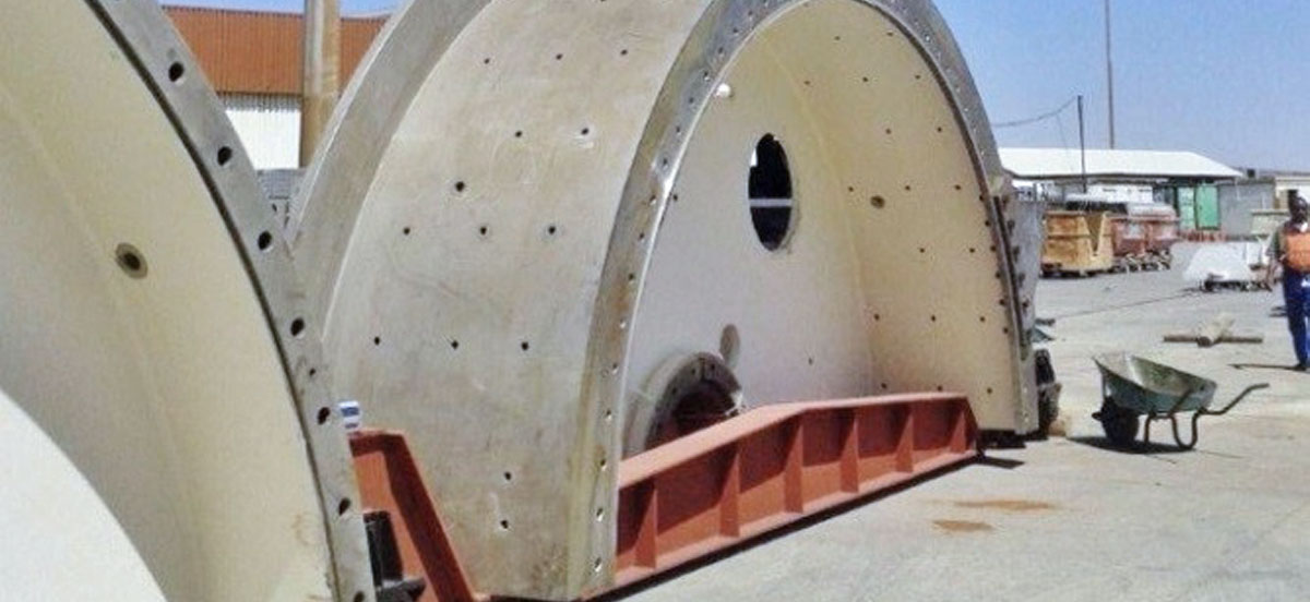
However, in the matter of modernising a 5.5 m-diameter double-drum winder, located 1,981 m below the surface, underground-transportation of the large mechanical components becomes a challenging problem that calls for specific solutions. This modernisation implied the delivery of two new 5.5 m-diameter x 1.6 m drum units as well as a new drum shaft with a mass of 37 tonnes and a length of 8.5 m. The afore conducted risk assessment for the necessary underground-logistic and transport operations assessed, amongst others, the following listed challenges that called for careful planning and were finally successfully met by WINDER CONTROLS South Africa as contractor:
- Can the new drum units drive shaft be lowered down the shaft without difficulties?
- Is the suggested route, the equipment has to follow large enough to enable safe and secure transport?
- Will the length of the drum shaft safely and securely get round the various bends along the route?
- Is there a risk that the new drum units and shaft might damage other equipment, for example, pipes, cables and pumps?
- What about availability, engineering and inspection of attachment means?
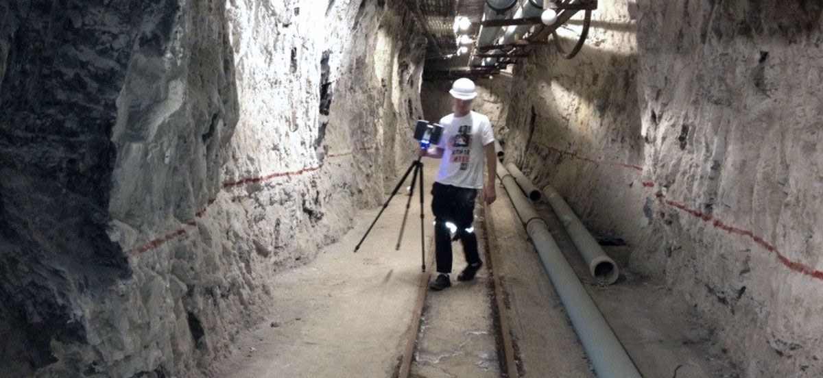
In order to ensure a safe and secure transport of these large components from the surface to the underground winder cavern, the entire transport route and all surrounded premises, the components had to pass, were inspected.
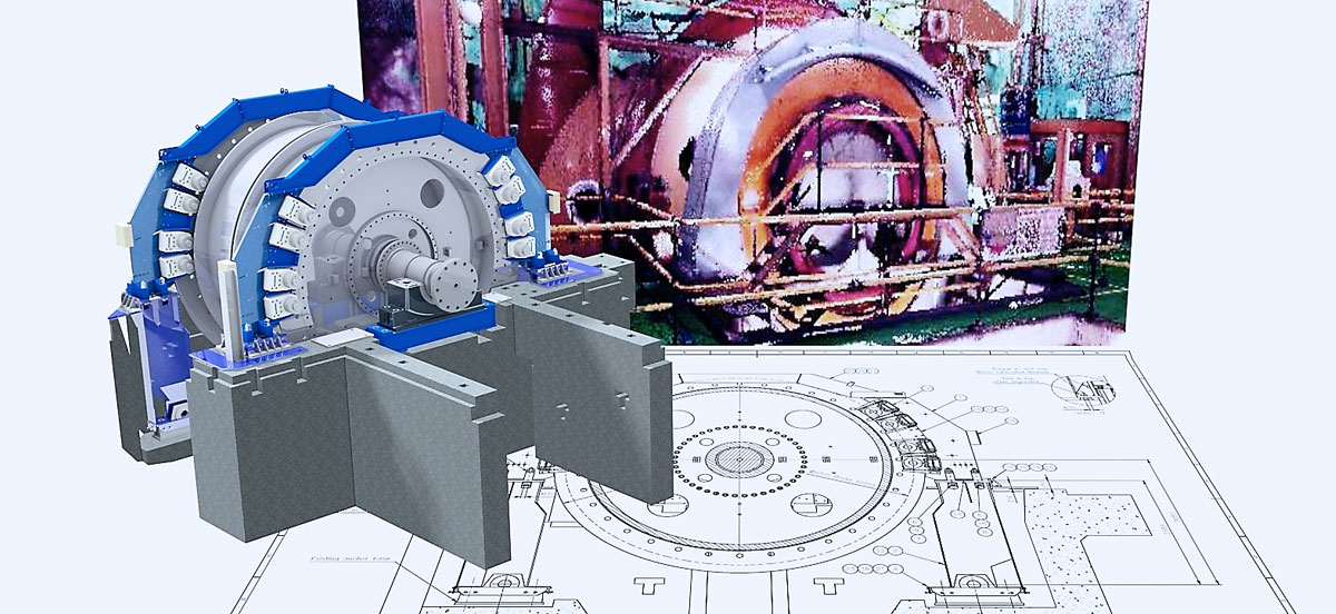
With the help of laser scanning technology WINDER CONTROLS prepared 3D images, modelling all the areas the components had to be carried through. This enabled to simulate the procedures during the so-called "underground transport services", to guarantee a free, unobstructed and fast transport at a later stage. The collected 3D point cloud data provided a clear 3D video image of the areas. 3D models of the drum segments and of the shaft could thus be digitally manoeuvred through the critical areas.
The information gathered during this process clearly indicated where and to what extent the component assemblies would be obstructed by the fixtures and fittings along the way and at what points fixtures and fittings, installed by the customer, had to be moved out of the way or removed altogether. Furthermore, clearly defined parameters were required for the construction of special attachment means and transport rollers. Special undercarriages (so-called deep-bed swivelling bogies) were built to enable the transport of the drum components from the stop shoulder in the shaft through to manoeuvring along the transport routes. It was extremely important to keep the balance point of the subassemblies as low as possible while simultaneously ensuring that the equipment was strong enough to support the load of the components and also to manoeuvre through the narrow points.
Therefor the carriages and attachment means were bolted to the drum segment and, after a test prior to the scheduled plant shutdown, were vertically lowered into the shaft. The specially developed transport rollers were bolted straight onto the shaft coupling flanges and were arranged in a way to enable the necessary tilting during the suspension of the driving shaft into the shaft. As with the drum halves, the drive shaft could be lifted on one side to enable lateral movement in confined areas.
In summary, it is quite obvious that the information gathered by the 3D spatial scanning system was decisive for the success of the project execution. The unavoidable downtime of the shaft system was considerably reduced by the chosen measures, and necessary labour time to clear the transport route as far as possible was limited to a minimum, as only the predefined parts of the infrastructure had to be removed.
For further technical data, please go to References.